- 1. Purpose
- 2. Scope of Application
- 3. Duties of the Operator in The Solar Energy Production
- 4. Content
- 4.1 Cutting EVA
- 4.2 Cell Sorting for Solar Energy Production
- 4.3 String Welding the Solar Panel
- 4.4 Lay Up the Solar Panel
- 4.5 Mirror Surface Inspection on The Solar Photovoltaic Cell
- 4.6 EL Testing on the Solar Panels During the Production Process
- 4.7 Lamination of the Solar Panel Kits
- 4.8 Trimming During the Solar Panel Production Process
- 4.9 Frame Up the Photovoltaic System
- 4.10 Junction Box Fixing in the Solar Panel Production
- 4.11 Cleaning a Solar Panel During the Solar Manufacturing Process
- 4.12 Safety and Performance Test on Solar Panel Energy Production
- 4.13 Performance Testing During Solar Panel Energy Production
- 4.14 Testing Requirements for Solar Panel Manufacturing Process
- 4.15 SOLAR PV CELL PRODUCTION PROCESS FLOW CHART
- 4.16 Additional Information on Solar Power Energy Manufacturing Process
1. Purpose
How are solar panels made?
This document gives guidelines on the solar panel production process.
It also gives details of the relevant raw materials that are needed by solar panel manufacturers in the manufacturing of solar panels.
2. Scope of Application
Where will the document be used?
The document will be used for the photovoltaic module production workshop of Shandong Jinpo Solar Technology Co. Ltd.
3. Duties of the Operator in The Solar Energy Production
What are the duties of the operator?
The operator is fully responsible for the whole operation process.
All the activities of the operator should be in accordance with the stipulated instructions.
The leader of the production class checks and rechecks the whole operation process.
4. Content
4.1 Cutting EVA
4.1.1 The pictures below represent the cutting EVA.
As you can see, each component is equipped with 2 pieces. One piece is needed to open both sides from the middle point.
The opening should be done from a height of 80mm. It has the height of 80-85mm which is at the wire hole.
4.1.2 Cutting TPT (Back Plate)
Specifications: 1000mm(800)*0.32mm,General 100m\ roll, white)
Cutting TPT with the same method of cutting EVA, size as follows:
1654*1000 / 1970*1000 / 1594*820
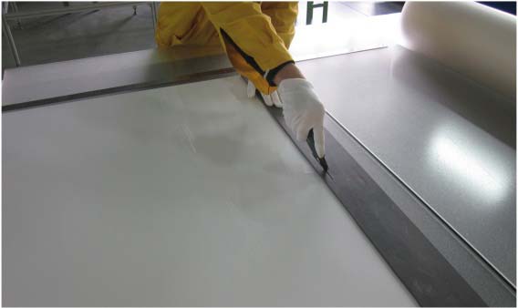
4.1.3 The Opening of Lead Out Wire During Solar Panel Production
Steps:
- The back plate (TPT) is flattened on a glass platform
- Position the template on the TPT then use the knife to confirm the opening
- Cut well the TPT and level it on a turnaround car
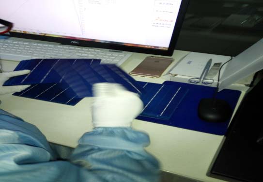
4.2 Cell Sorting for Solar Energy Production
4.2.1 Sorting by Appearance
Here are the steps to follow:
- In the registration form, fill the content of the outer box label of the cell into the incoming material.
- After opening the box, confirm whether the specification is in accordance with the label content.
- Inspect the solar panel cell based on key features such as appearance and quality. Ensure that the solar cells are in the accordance with the national standard.
- Turn the solar cell front up and view it from different angles.
- Put the cells that have the same color and size in different groups. Each group should contain at least 36pcs, 60pcs and 72 pcs of solar cells. Put all the groups in the material tray.
- Fill the solar pv production process card and stick a barcode on this card.
4.2.2 Technical Requirements in the Solar Cell Manufacturing
Kindly take note of the following technical requirements during the solar panel production.
- Ensure that there should be no mistake of the cell grade
- The number of cells on the solar panel should be accurate
- The color and the size of the cells should be consistent.
- Be careful with the humidity levels. It should be less than 65% per day. The temperature range should be around 25 ±5. Of course, open the dehumidifiers when necessary.
- Calibrate the standard cell calibration simulator after every 2 hours.
4.3 String Welding the Solar Panel
4.3.1 String Welding Procedures during Solar Panel Production
Follow these procedures when string welding a solar panel:
- Check for the defects on the cell. These include improper angle, lack of edge, and the poor state of the welding belt.
- Put the solar panel cell into the material box and start to circulate. While doing so, observe the following:
- Whether it is normal in welding plate, light welding powder and temperature of the string welder.
- Whether the scaling powder is smoothly and within the allowable range
- Whether has the cold solder joint, leakage welding, partial gate, irregular arrangement phenomenon.
- Be keen to observe cell whether it has the scaling powder residual and clean the scaling powder crystal in time.
- Observe whether the material and position of the series welder, fixed location ,sucker , cell box position, clip working position are normal or not. .
- Check whether the string is normal or not.
- Timely replacement of welding belt and scaling powder to supplement the cell.
4.3.2 Technical Requirements for the Solar Energy Production
Here are other technical requirements that you should observe:
- Carry out a self-checking procedure.
- The thin coated belt should be smooth and bright. It should not offset the main gate line. Also, there should be no residual bump or rosin joint.
- When using the string, the end of the tin coating belt should not have an excess solder.
- There should be no continuous welding between the solar cells. The gap between two cells should be 2.0 ±mm.
- Be aware of the humidity. It should not go beyond 65% per day. Open the dehumidifier when the humidity is high.
- You should also be careful with temperature. It should be 25±5 degrees Celsius.
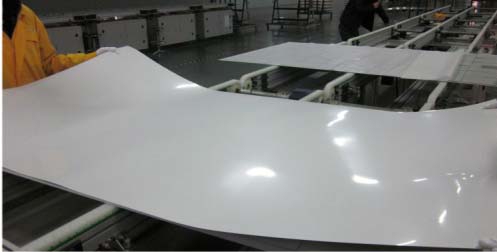
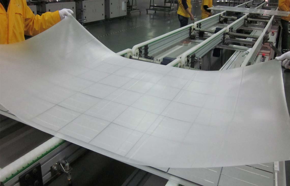
4.4 Lay Up the Solar Panel
Here we are going to focus on the procedures for laying up the solar panel.
- Check for any defects on the glass. These defects include chippings, impurities bubbles, dust, scratches and many others.
- Check to ensure that the grain is not upward.
- Clean the glass using an air gun. This process should be able to eliminate dust and debris on the glass and EVA.
- Confirm the specifications of the EVA and ensure that they are correct. Use transparent EVA to carry out the process.
- Arrange 6 strings of cells on an EVA depending on the direction of the electrode as illustrated in the pictures 1 and 2.
Follow the following steps when arranging the solar cells:- 6 strings cells front downward, the edge of the upper end the lower end is in a straight line. The distance from the upper end and the lower end of the cell to the edge of the glass should be uniformity (26mm±2mm, 125cell)
- The distance between the string and string of the 6 strings cells is 3mm
- The distance of the left and right cell to the edge of the glass is 18.5mm±2mm, according to the size of the drawing when the size is in error.
- Check whether the interconnected tin belts that are at the ends of the solar cell meet the requirement in the drawing.
- Connect the confluence belt to the 6 strings of the solar cells as illustrated on the picture 3.
While connecting, take note of the following:- Ensure that the distance between the upper and lower end of the confluence belt is 5mm.
- The lead-out wire which is pressed on the confluence belt and intersected to 90 degrees, it should not exceed the confluence belt.
- At the intersection of vertical welding solder joints, which will use tweezers fixed solder joints, gently lift, complete with electric iron welding.
If it is needed an appropriate amount of scaling power will be added to ensure that the welding spot is bright, smooth and full.
The height of the welding surface should not exceed the layer of the first tin to be coated.
Pic 5 and Pic 6
- Weld four pieces of lead-out wires on a vertical balance and illustrated on the picture. Consider adding an extra interconnected tin belt.
- Based on the location specified on the diagram, position the insulation tape between the cell and the lead-out wire.
Consider laying the insulation strip between the confluence strip and the barcode strip.
Stick an adhesive tape to the a3*b3\e3*f3 position to prevent the moving position of the insulation belt and the confluence belt - Check the gap of each part that you have assembled to determine whether there is a change in the distance between them.
In case there are some changes in the distance, adjust them to fit the requirement in the drawing.
Carry out an inspection and remove all the sundries that may be remaining.
4.4.1 Technical Requirements In a Solar Cell Manufacturing Process
While at this stage of the solar cell manufacturing process, try to stick to the following technical requirements:
- The gap between the solar cell and the string should be equal or more than 1mm but less than 5mm.
- The lead-out wire position should meet the requirements of the drawing .
- There should be no welding slag, tin coated belt oddments , hair, fiber and other sundries on the plate .
- The solar panel plate should not have hair, fiber welding slag, coated belt oddments and other sundries.
- The temperature control of the soldering iron should be attached on the EVA.
- You can fill the data in the Solar Cell Production Procedure Card.
- As usual, be careful to observe the humidity and temperature.
The humidity should not go beyond 65% per day and temperature should not exceed 25±5.

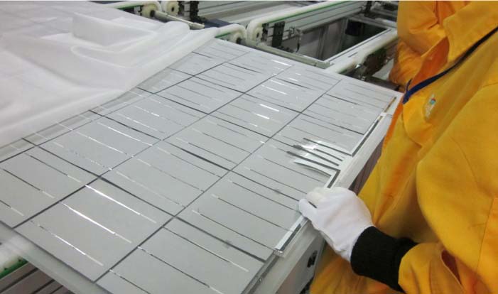
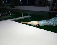
4.5 Mirror Surface Inspection on The Solar Photovoltaic Cell
Before you declare your photovoltaic cell ready, you need to carry out a mirror surface inspection.
This step will help give you an assurance that the mirror of the solar panel is in a perfect condition.
Here are the steps to follow:
- Ensure that the mirror surface is sparkling clean. You can use alcohol wipes to ensure that it maintains this status.
- Get rid of solid materials such as hair dust and other impurities that can affect the performance of the mirror.
- Inspect to determine whether EVA was used correctly. The bottom layer should be very transparent.
Use an ordinary transparent EVA on the top layer. - Check to determine whether the EVA and backboard are positioned in the right places.
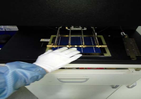
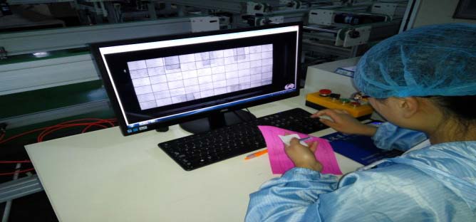
4.6 EL Testing on the Solar Panels During the Production Process
Here are the steps to follow when carrying out EL testing on a solar panel:
- Open the computer and double-click the EL software icon.
- Select the parameters which are under the standard mode settings
- Put the components of the solar panel in the EL camera’s test table. Ensure that the glass of the solar panel kit is facing downwards.
- Start the camera then take a picture

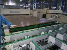
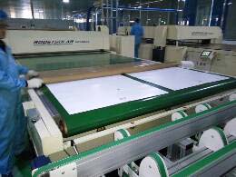
4.7 Lamination of the Solar Panel Kits
4.7.1 Typesetting Steps During the Solar Cell Production Process
Follow the following steps carefully when typesetting solar panel kits.
- Clean the working area thoroughly. You should also clean basic components such as laminator and conveyor face.
- Switch on the power supply of the laminator. Open the power key separately, and press the heating button after the computer starts and enter the laminating application program.
Ensure that the laminator is preheated, according to the different laminator set the hot plate temperature, Reference file JP/QE40312-2016. - When there is a drastic rise of temperature, the laminator will run idle to ensure that the equipment remains in a perfect condition.
You should then move the components to the laminator’s conveyor belt.
Cover the laminator with a high-temperature cloth. Ensure that this cloth is clean.
Once covered, press the start button so as to initiate the feeding process.
When using a vacuum pumping method, monitor the gauge to ensure that it is not more than 20KPA in 30 seconds.
Ensure that all the components of the solar panel are running smoothly. Otherwise, do not hesitate to inform the supervisor in case of any abnormality.
Check figure 1 and 2. - Shut the cover in its required place and in good time.
- After doing the lamination and curing, your laminator will automatically open the upper cover. It will then transport the solar cell to the conveyor belt.
- An operator who is properly geared (wearing thermostability gloves) will quickly connect the high-temperature cloth and components that connect to the discharge platform.
- After discharging, the operator will then wait for the solar cell to cool. This will last for like 10 minutes.
The other operator will then give a hand in the lifting of the solar cell out.
The two operators will then clamp both sides of the solar cell. They will then roll it over to one direction for inspection.
4.7.2 Fill in the Solar Cell Production Procedure Card
4.7.3 Technical Requirements of the Solar Energy Production Process
Kindly take note of the following technical requirements to follow when using solar energy.]
- The black plate should completely cover the glass
- Should do a self-checking
- There should be no fragments
- The distance between cell strings should be at least 1mm but not more than 5mm.
- Ensure that there are no bubbles on the surface of the solar panel.
- As discussed earlier, you need to be vigilant with temperature and humidity.
The humidity should not beyond 65% and the sun between 24 and 28 degrees.
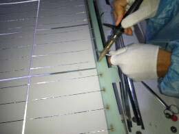
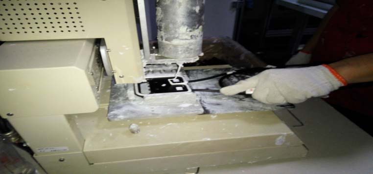
4.8 Trimming During the Solar Panel Production Process
4.8.1 Steps for Trimming a Solar Panel
Follow the following steps when trimming the solar power system.
- Start by fitting the solar cell into the trimming platform. Ensure that its back is facing upwards the stretch the platform to a length of 10-20mm.
- Ensure that you wear your gloves while pressing the solar cell. Let your left hand do the pressing as your right hand holds.
Position the cutter high above the solar cell at an angle of 25 degrees. - From one end of the glass firstly gash a notch .then along the glass with uniform speed push to the top . (as picture 1)
- Cut the other three sides of the solar panel
- Put the four sides that were cut off into a plastic bag then record the readings.
- In case the cutter blade gets damaged, do an immediate replacement. This will ensure that it does not affect the TPT which is made of the glass surface.
- Turn the solar cell and inspect it fully. At this stage, you can put a qualified and unqualified turnaround car.
- Fill in the <Cell Production Procedure Card >
4.8.2 Inspection Requirements of Solar Cell Manufacturing
Please adhere to the following specification requirements:
- Self-checking
- There should be no fragments, tin coated belt shift and any metamorphism
- The width of the first layer should be less than 0.5mm.
The length should be less or equal to 30mm and its thickness should be 2mm.
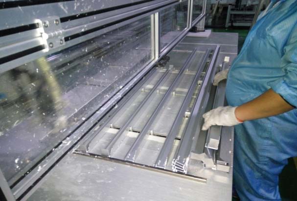
4.9 Frame Up the Photovoltaic System
Here we look at the procedures for putting the solar panel into the frame.
4.9.1 Steps
Here are the definitive steps that you should follow:
- Start by debugging the frame as instructed in the equipment regulations.
- Debug the frame according to the size of the component
- Install the aluminum allow on the spreading machine. This will facilitate automatic glueing.
Put the component glass on the frame facing downwards. Flat up and frame up the machine.
Ensure that your aluminum frame allow is made of silica gel, and its quality tested and proven.
Also, all the four sides of the frame should be at the same level as illustrated in the picture 1.
- The operator should confirm that it is in safe condition then press the button. This will make the cylinder on both sides to automatically squeeze the frame.
Push the aluminum frame slowly to the other end then clamp it. - While the two cylinders are in operation, the operator must check the alignment of the glass edge.
The edge should be properly aligned with the aluminum frame that you have just installed. - After you are done with the framing bit, try to manipulate the button, cylinder, head restriction, hydraulic planish button, and planish head.
Remove the cell component and check whether the aluminum frame is properly aligned in its position.
The side angle of the component should be at 90 degrees.
4.10 Junction Box Fixing in the Solar Panel Production
We are going to focus on how to fix a joint box into a solar pane.
4.10.1
To fix the box follow the following steps:
- Glue the bottom end of the junction box. Once you have pressed the junction box on the backboard, spill the silica gel around it. Pic 1
- Load the confluence strip into the bayonet of the junction box. Use screwdriver to check whether the clamp is properly attached or not.
- Fill in the <Cell Production Procedure Card >
4.10.2 Technical Requirements of Solar Photovoltaic Cell
- Self-checking
- Check for the appearance of the aluminum frame and take note of any blemishes such as scratches.
- Check on the mounting hole for leakages. Ensure that the mounting hole matches with the one on the diagram.
- In all the measurements, give an error allowance of ±1mm unless it has been illustrated.
- The temperature of the soldering iron should be controlled to stay within 400±5
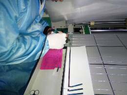
4.11 Cleaning a Solar Panel During the Solar Manufacturing Process
One critical step that top solar manufacturers must adhere to is solar cleaning.
- Roll back all the previous processes and take note of all the defective products. Return them to their manufacturers.
- Use a PCB board to scrap off the excess silica gel that has accumulated on the aluminum frame.
You can do this by dipping a piece of clothe in alcohol as illustrated in picture 1and 2
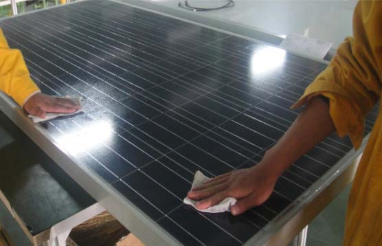
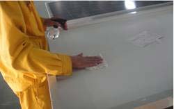
- Get rid of all the residual EVA on the backboard using a soft material as illustrated on picture 2.
- Scrub the backboard using a clean cloth that has been soaked in alcohol.
Be careful not to interfere with lead-out wires.
4.11.2 Technical Requirements When Cleaning a Solar Panel
- The final appearance of the solar power system should be clean and bright.
It should not have any elements of silica gel or other impurities. - The backboard of the solar panel should smooth, neat and intact.
- Start by cleaning the frame before proceeding to other components of the solar equipment.
4.12 Safety and Performance Test on Solar Panel Energy Production
Is the PV panel capable of producing energy as required?
Does it meet the required safety measures?
To answer these questions, you need to carry out a safety and performance test on the solar panel kit.
We are going to look at these two aspects; performance and safety tests during the solar panel manufacturing process.
4.12.1 Test of Pressure Resistance Earthing Resistance and Insulation of a Solar Panel Kit
Before carrying out any test, ensure that you wear insulating rubber gloves.
Also, put an insulating rubber beneath your feet when operating the equipment.
4.12.2 Functional Inspection of Safety Regulation Tester
- The first step involves conducting an inspection on the tool that you want to use.
- Open the tester switch then select group item “dj”. This will enable you to start testing.
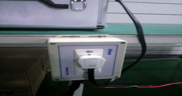
- Insert the plug of the spot inspection into the 220V electrical socket
- Complete the connection as shown in these pictures.
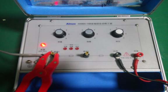
- Press the start button then compare the results after testing
- The results will be qualified if they fall within a certain range. They will be unqualified if they fall out of the specific
- The measures after instrument lose efficacy.
- If you find the test instrument lose efficacy ,we should evaluate the effectiveness of test results which from last time operation test to this time operation test . and take necessary measures .
- Make the necessary adjustments on the equipment so as to meet the requirements .
- If the adjustment cannot meet the requirements, then disable the equipment ,stick the stop identification ,and use the similar calibrated equipment
- If necessary replay the products which had been tested and retest , or entrust the user who has the detestability to test .
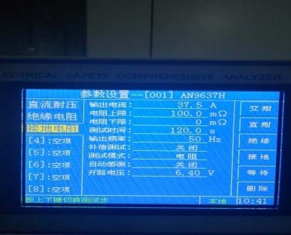
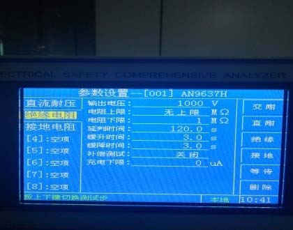
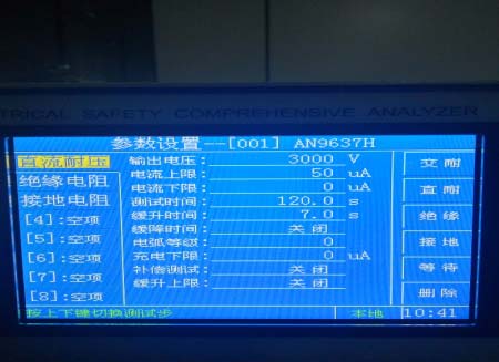
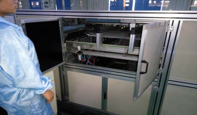
4.12.3 Component Test Steps in Solar Panel Production
- When testing the components of a solar panel, ensure that you are properly insulated.
Wear gloves and insulating pads to protect your body from the electric shock. - Copy the following parameters to set the instruments
-Earthing parameters 1
-Insulation resistance parameters
-DC voltage resistance parameters - Pair the red plug of the instrument with the positive pole of the component. On the same note, you should par the black plug with the negative pole of the component.
- Make the No.1 pliers clipped in the position of earthing hole where there is an earthing sign.
- Make the No.2 pliers clipped in opening place on the other end frame of the junction box
- Press the “start test” key to begin testing
- After testing ,the green light is qualified, the red light or yellow light is not qualified.
- Record all the test results.
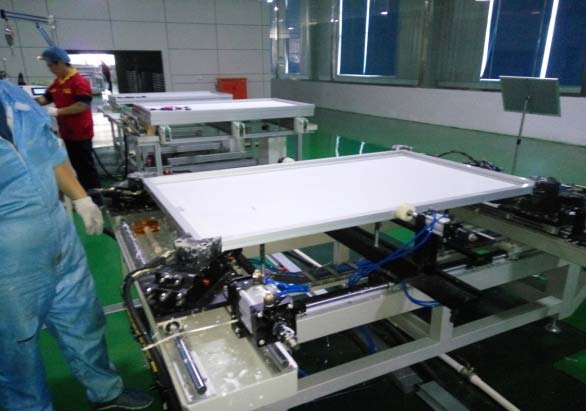
4.13 Performance Testing During Solar Panel Energy Production
4.13.1 Testing Steps
- Switch on the computer then launch the Test software icon.
- Switch on the simulator and light source switch to check whether the voltage of the power source is 260-280V
- Position the solar panel plate on the glass surface of the testing platform. Ensure that the plate is facing downwards then mark its middle position.
- Clip the red electrode clamp to the positive pole of the solar panel plate. The black electrode should be clipped to the negate pole. While doing so, ensure that the exposed e lead-out wire does not come into contact with electrode joint or any other conductor.
- Click the start button and you will notice that the device will flash.
- Get rid of the substandard plate then collect components to be tested.
- Click the start button and check if all the parameters available meet the requirements

4.14 Testing Requirements for Solar Panel Manufacturing Process
- Before you start with the testing, ensure that the following conditions are met:
- Light radiance of 100W/sqmetres
- Test temperatures of 25-2/25 degrees Celsius
- CAN15 ground solar spectral irradiance distribution.
Set up different solar cell plate components depending on the requirements.
- Correct the time on the standard plate after every two hours.
- Fill the Cell Production Procedure Card
- Ensure that the humidity should not exceed 65%
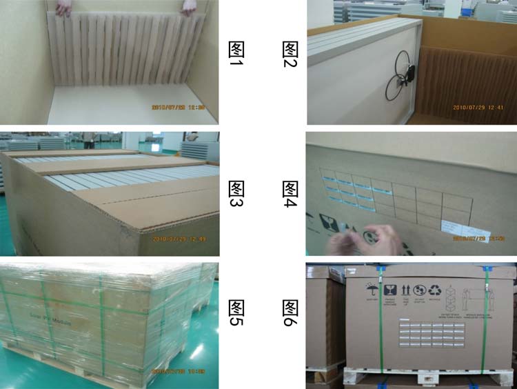
4.14.1 Packing Measures for A Solar PV Panel
- Assemble the packing carton according to the specified instructions.
- Asses the state of the carton box to determine whether it is damaged or not
- Spread the carton on the tray then place it in the bottom and side of the plate. Ensure that the middle and bottom parts of the plate don’t come into contact with the perimeter of the square as in picture 1
- Unbox the circulation card then store it.
- Pack the connector of the solar panel kit together with its junction box
- Get a partner to assist you lifting all the components of the solar panel kit and place them on the side plate of the packing box. The outermost two pieces of the glass should be positioned outwards.
- Once the carton is full, you should add the upper side plate. This step may not be applicable to the 72pcs and 125 components.
- Add the side of the carton at a point where the form sticks to the barcodes.
- Close and cover the carton. Bind all the three packing belts on the front of the carton as illustrated on the picture 5. Bind the packing belts on the side.
- Put the whole package in the electric forklift, switch the position of the forklift then transport to the warehouse for storage.
4.14.2 Packing the Photovoltaic System in Solar Power System Manufacturer
- Check the state of the packing box to ascertain whether it is damaged or not.
- Check on the specification of the solar cells. Ensure that they have barcodes
- Check on packing belt to ensure that it is not loose.
- Take the EVA suede that is more than 5mm than the eradication area.
- Upward fill the eradication area and upward fill in the eradicating area is well positioned for iron spot welding.
- Weld the solar cell
- Fill the area as shown in picture 5 with one piece of EVA to allow it accommodate an electric soldering iron.
- Take a piece of EVA and pave the suede to the cell that leads out to the confluence. Connect the test circuit for conducting the test. Proceed if the test is successful.
- Take a piece of black plate and position its face downwards so that it leads to the confluence strip. Fix it with a gummed tape.
- Laminate it at temperatures of 135-142 degrees Celsius. Pump 5 pressure points .
- If there is no need to replace the solar cell, you should proceed to remove all unwanted substances then refill it.
4.14.3 Rework During Solar Energy Production Process
Here are the steps for reworking on a solar panel:
- Put the component into a rework station and heat it for 30 minutes
- Peel off the TPT back plate as shown. The peeling area should be 200mm by 200mm
- Remove the defective solar cells and get rid of excess EVA.
4.15 SOLAR PV CELL PRODUCTION PROCESS FLOW CHART
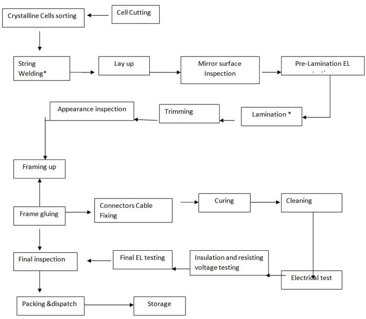
Note: the “*” for the special process
4.15.2 Video of Solar Panel Power Production Process
4.16 Additional Information on Solar Power Energy Manufacturing Process
- http://www.tsecpv.com/en-global/solar_knowledge/index/zero_house_02
- https://www.btu.com/products/solar-cell-manufacturing-equipment/
- http://www.madehow.com/Volume-1/Solar-Cell.html